
Back in February 2018 a small Fielding & Platt engine appeared for sale on Facebook Market Place. When I first saw it I passed it by as the pictures made it hard to tell just what it was, but upon closer inspection later in the day I realised just how unusual the engine was and that it appeared to be largely complete. Contact was made with the seller and after a little haggling a deal was done. The engine was located in Abergavenny, Wales, so collection was organised for a couple of weeks later. Fielding & Platt oil engines are not a common sight, and the small ones are especially unusual. This model is rated at 1/2nhp and we think originally had a compressor cylinder mounted in the side of the crankcase presumably used to air start a larger Fielding engine.
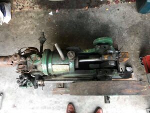
The engine as advertised on Facebook back in 2018.
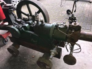
Once collected it was clear that although the engine had been previously restored & rallied, it had suffered some neglect in recent years and needed freshening up before I would be able to rally the engine. Upon getting the engine home it was given a quick wash over and once all of the oil & dirt was washed off the paint work was found to be in reasonable order. It was then decided that a new trolley & cooling tank would be needed, but it was otherwise hoped that the engine would not need much work. Sadly, this proved to be wishful thinking, but more on that later. The engine was then put away in the shed as I was in the process of restoring a Lister DK lighting set and didn’t have space in the workshop to have 2 projects on the go at the same time.
Back home after a quick wash to get the worst of the oil and grime off.
Fast forward to the following Autumn and with the Lister DK set finished, it was time to pull the Fielding into the workshop and make a start on tidying it up. As soon as I started to strip the engine down to better assess the general condition and give everything a more thorough clean, it became apparent that this was not going to be a quick & easy job. It was quickly obvious upon closer inspection the engine had a fuel pump from a Lister Junior poorly adapted to replace the missing original. Other issues found included the majority of the pins and shafts in the governor mechanism were badly worn/corroded. The side shaft and con rod had been badly attacked with an angle grinder to get rid of some heavy pitting. Worse still inspection revealed that the grease cup on the big end was not original and an oil ring should be fastened to the crank web to feed oil into the big end. This oil ring was missing and was expected to prove the biggest issue with the rebuild. What had started out as a trolley/cooling tank build, quickly became a full mechanical overhaul.
The first job was to make the new trolley as planned. A set of 4 wheels was picked from our stock and then the task of machining axles and sorting the timber work began. The timber was ordered from R.H. Chappelow of York. They supplied some lovely Sapele at a very reasonable price. The axles were made from 40mm box section with round bar welded into the ends to take the wheels. The bar needed turning down to fit the wheels, so I made a trip to the parents’ house to use Dad’s Raglan Little John lathe, as my lathe is too small for this sort of work. A couple of hours later and I had a bin half full of swarf & 4 stub axles made to fit the wheels. The stub axles were then welded into the box section and a steel disc welded to the box to act as a turn table on the rear axle. The next job was to assemble the timber and to start coating it. I use Osmo Wax Oil and find that it gives an excellent finish and highlights the grain in the timber. After 3 coats of Osmo, the timber was ready. The metal work had also been painted during this time, so now everything was ready to assemble.

Turning a stub axle down to fit the wheel.
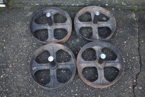
The wheels with finished stub axles.
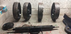
The trolley iron work after having its final coat of black paint.
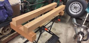
The timber all rubbed down ready for the first coat of Osmo wax oil.
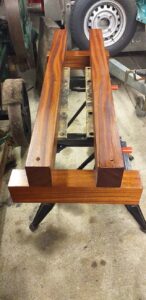
The colour and grain pattern is showing through after a couple of coats of Osmo.
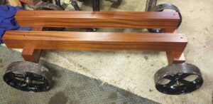
With the painting of the ironwork & the wax oil coating of the timber completed the trolley was loosely assembled.
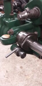
With the trolley finished it was time to get on with the engine. The flywheel, piston, rod & crank were removed and luckily the mains & big end shells were found to be in reasonable order. Certainly nothing a bit of scraping couldn’t solve. The biggest issue was the oil rings for the main bearings. These were anything but round and resembled an egg more than a circle. These would need some serious work to get them back in shape so they could spin with the crank and feed oil up to the main bearings from the reservoir below. Once apart the task of assessing the damage to the side shaft & con rod began. First of all, we looked at the side shaft as it was thought this would be the easier one to tidy up as it could be skimmed undersize in the lathe. Due to the length of the rod we needed to use the fixed steady to hold it securely. We only skimmed the exposed parts of the rod, which is where it had been abused with the angle grinder by a previous owner. To get rid of the worst of the grinding marks, we had to skim over 0.160” off the shaft. There are still a few minor marks now, but it is far better than it used to be. The con rod was going to be a tougher job as skimming was not really an option due to it having a taper over the length of the rod. Instead, several hours were spent with emery cloth polishing the rod up to get rid of the worst of the marks. It was slow work but it’s now impossible to tell that it had once lost a fight with an angle grinder.
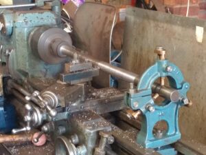
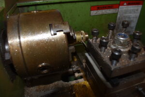
Skimming the side shaft, on Dad’s lathe.
With the side shaft & con rod sorted, attention turned to the rest of the engine. As previously mentioned, all of the pins/shafts for the governor mechanism were badly worn, so replacements were made, as were the roller & shaft for the decompression/starting cam follower. As these were small parts they could be done on my little Warco lathe. The nuts for the main bearing caps were modern zinc plated things, so I decided to make new replacements to the pre-war full nut sizes. These were made by ordering the right sized hexagon bar and drilling it out on the lathe, adding the chamfer to the top of the nuts and then tapping in BSW. The decision was also made to replace the big end bolts as what was fitted was a pair of M12 socket head bolts. To replace these, I started with a pair of M16 hex head bolts. The hex head was turned down to round and the length of the bolt was machined down and threaded ½”BSW. Once complete new nuts & lock nuts were also made.
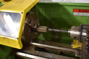
Making the new main bearing cap nuts. Drilling the hex bar out ready for tapping.
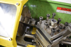
Turning the chamfer on to the top of a nut.
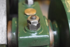
A test fit of the new main bearing nuts.
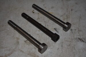
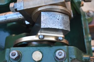
One of the M12 socket head bolts fitted to the big end. Seen with the 2 new 1/2″BSW bolts which I made.
The new shaft, roller and taper locking pin for the decompression cam follower.
With several new/replacement parts made I began loosely re-assembling the engine to check everything out. One job I had put off as long as possible was the fuel pump. Closer inspection found it to be a poor fit in the clamp bracket and the plunger to have had the top ground off presumably to limit the amount of travel and thus the amount of fuel pumped when it was operated by the cam follower. The original plunger was replaced with a shorter one, with a ¼”BSF bolt threaded into the top, to allow the stroke of the pump to be adjusted. New O-rings were ordered to help seal the plunger and it was tested and found to pump fuel sufficiently. Finally, the rebuild was starting to take shape. A new fuel was tank sourced and a couple of brackets made, using 2 of the holes originally intended to carry the compressor cylinder. The flywheel gib key was a found to be too long and a poor fit and the head was quite chewed up. The head was tidied up, the key cut to the right length and it was then dressed to fit. This was a painstakingly slow process with the key needing to be filed/dressed and then checked with engineers blue. After a few hours it was seating well, so it was knocked in tight.
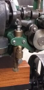
The Lister Junior fuel pump once re-fitted with the adjustable plunger stroke.
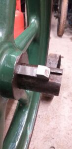
The flywheel gib key during a test fit.
While all of this work had been ongoing a cooling tank design was drawn up and sent to well-known engine collector Jeremy Heslop of York. Jeremy fabricated me a new cooling tank and had it hot dipped. Once collected the tank was offered up for a test fit. A new blow lamp stand was also fabricated, using an odd cast iron wheel as the base and a period lamp was sourced on eBay. The lamp was then given a good clean and once over. With all of this work done, I got carried away one afternoon and lit the lamp and thought it was time to try and fire the engine up. I was not hopeful that the engine would run as I had no idea if the pump was set correctly or if I even had the governors or valves set right. After about 5 minutes on the lamp, I primed the fuel pump and then cranked the engine over. At first there was nothing but after a few more swings of the handle the engine fired and burst into life. Well I wouldn’t exactly say it was living, but the engine was running. The garage quickly filled with smoke as the engine was getting far too much fuel and the governors were sticking so the fuel valve was striking every time. Once the fuel pump was adjusted and the governors freed off the engine settled down and ran reasonably well.
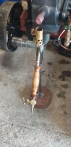
The blow lamp and stand.
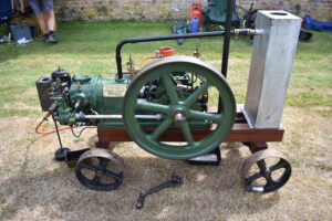
The rebuild nearing completion. The new cooling tank is loosely fitted and the pipework is made to size.
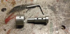
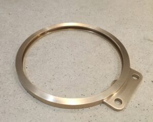
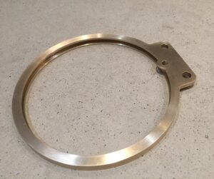
With the engine now running other missing components/parts that were not essential for the first run, needed to be made/sourced. The first of these was the crank guard. A guard was borrowed from the only other 1/2nhp Fielding known to survive in the UK and we took measurements and drawings. Following this Dad set about fabricating a new guard. More details on this can be found at (Link to Dads crank guard article). The next job was to re-make the missing oil caps for the main bearings and side shaft bearings. Luckily there was one original brass cap on the side shaft bearings, so this was used as a pattern. The replacement caps were made by turning a piece of brass bar, with the outer edge been knurled on the lathe. Once made they were parted off and fitted to the engine. The final piece of the puzzle was a replacement heat shield for the hot bulb. When I acquired the engine a half round sheet of metal was fitted with 2 flimsy brackets and hung off the vaporiser. This didn’t really work and kept falling off. A replacement was made using sheet steel folded and riveted together to offer a more substantial shield to protect from wind etc.
Parting off one of the new oil caps.
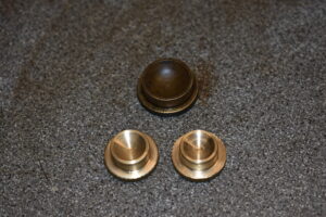
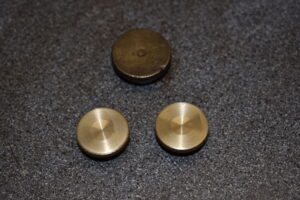
The 2 new main bearing oil caps and the original side shaft bearing oil cap which was used as a rough pattern.
The final job was to source a new oil ring for feeding the big end. The chances of finding an original were slim to none, so a new replacement was the only option. The biggest hurdle was that I didn’t even know what it should look like, and making one was beyond by capabilities. Contact was made with Trevor Hill who runs the Fielding archive, and he was luckily able to provide the original factory drawing for the oil ring. The drawing was not the easiest to read, considering it was over 100 years old and only small to begin with. A request for help in making the new ring was made on one of the Facebook engine groups and after a few days Colin Blackwell from BB Engineering Supplies of Barnsley offered to have a go at making the ring. Once the drawing was sent a price was quoted which seemed very reasonable. A few weeks later I received an email to say the ring was ready. It arrived in the post a few days later and was quickly fitted to the engine, along with the new crank guard which could only now be used following the replacement of the grease cup on the big end.
The new oil ring supplied by BB Engineering.
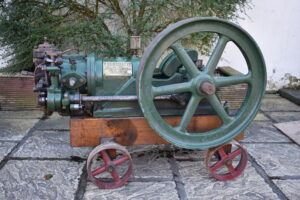
With the re-build finally finished it was time to take the engine out. It has now been rallied extensively over the last 18months and apart from a couple of minor issues has performed well. I owe a big thanks to my Dad Andy Milestone for his help with making the crank guard, Trevor Hill for supplying info and drawings from the Fielding archive, Colin Blackwell & Jeremy Heslop for helping with making parts and finally to Pete Miles, who let me take drawings/dimensions from his crank guard so that we could make a replica.
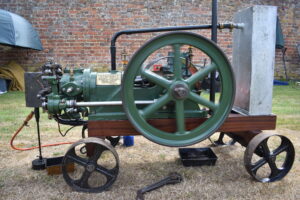
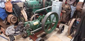
The finished engine enjoying a sunny outing at Breamore House in July 2023.
You must be logged in to like this post.
Country: GB