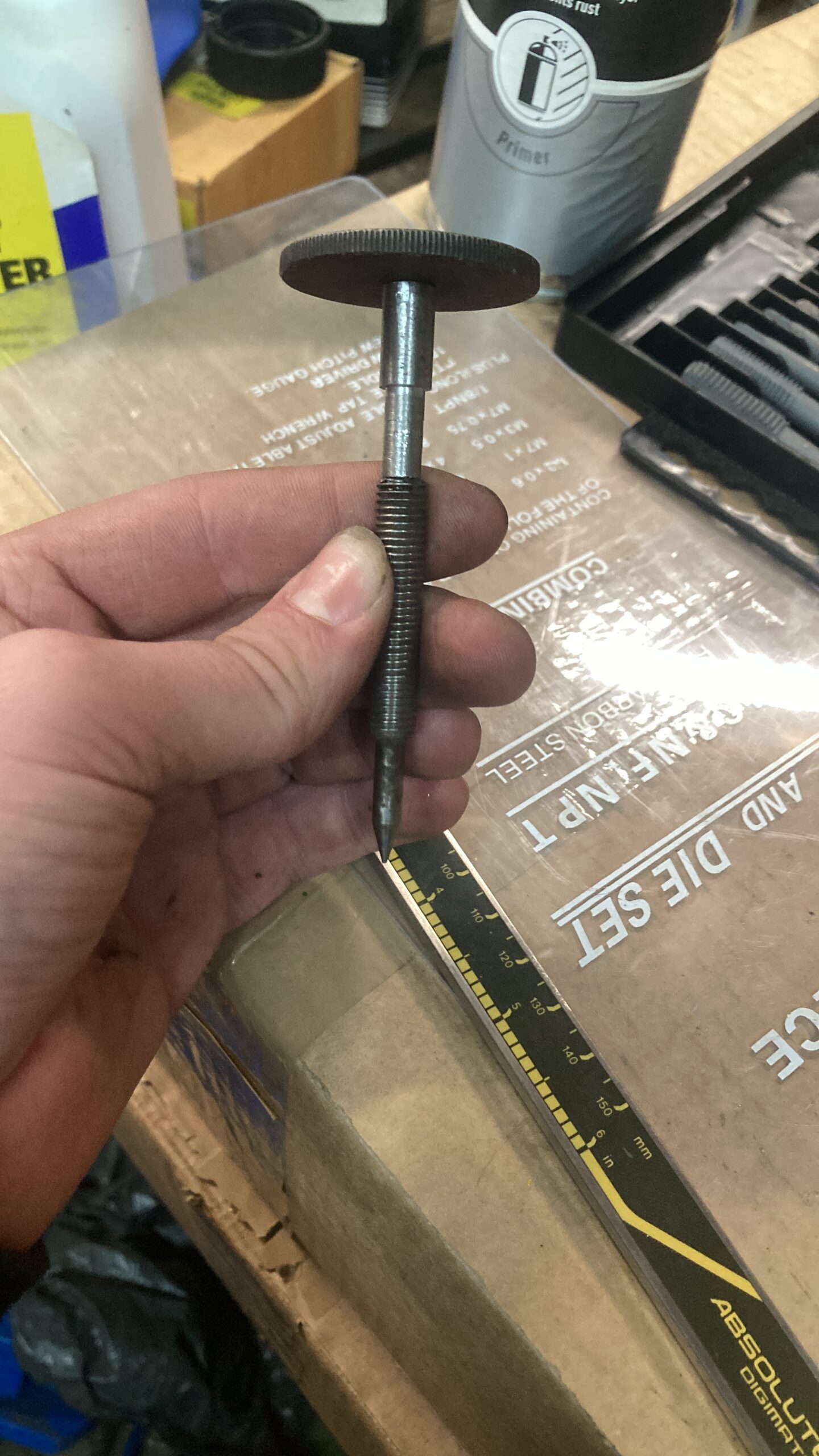
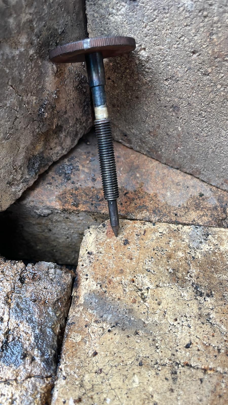
In an unfortunate chain of events while moving the 12hp AP around the yard a few months back, a strap slipped and caught on the fuel mixture needle, snapping it off. We were lucky enough to remove it from the fuel jet with a little heat and mole grips.
After successfully removing the broken parts, thoughts changed to how to rectify the issue. I began ringing round and sending pictures to some friends in the stationary engine world, but none had a spare in stock. I got one offer to remake the needle and shaft. saving the dial but with the equipment at hand to do this work myself, thought id have a go myself.
I had no real desire to mess with the needle itself or the screw thread, as this is ultimately the part that affects the running of the engine. So a plan was drawn up in which to joint a repair section to the end of the screwed shaft; that was smaller in diameter than that of the screwed shaft and able to be re-riveted through the dial.
Job 1:
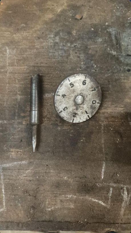
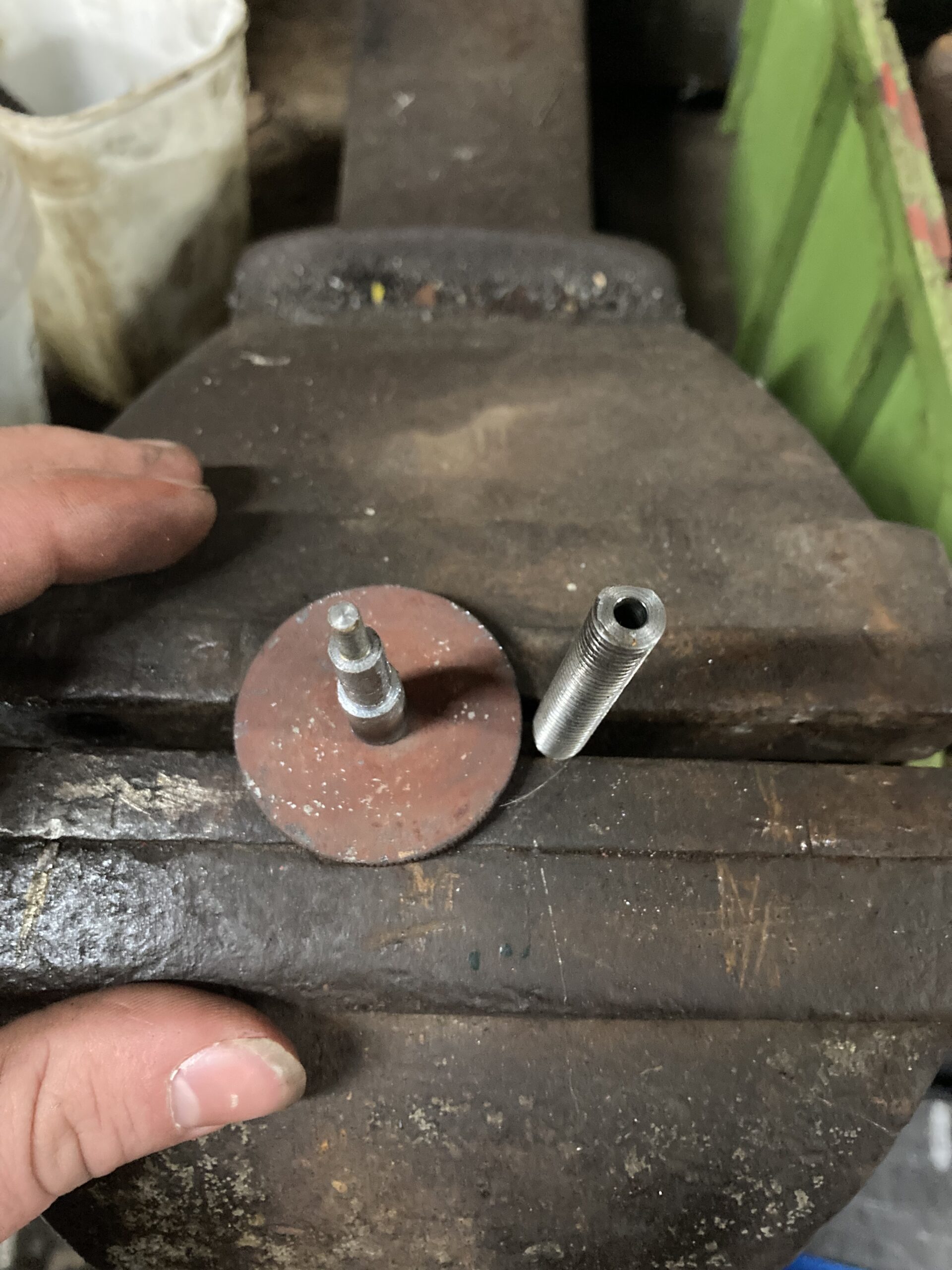
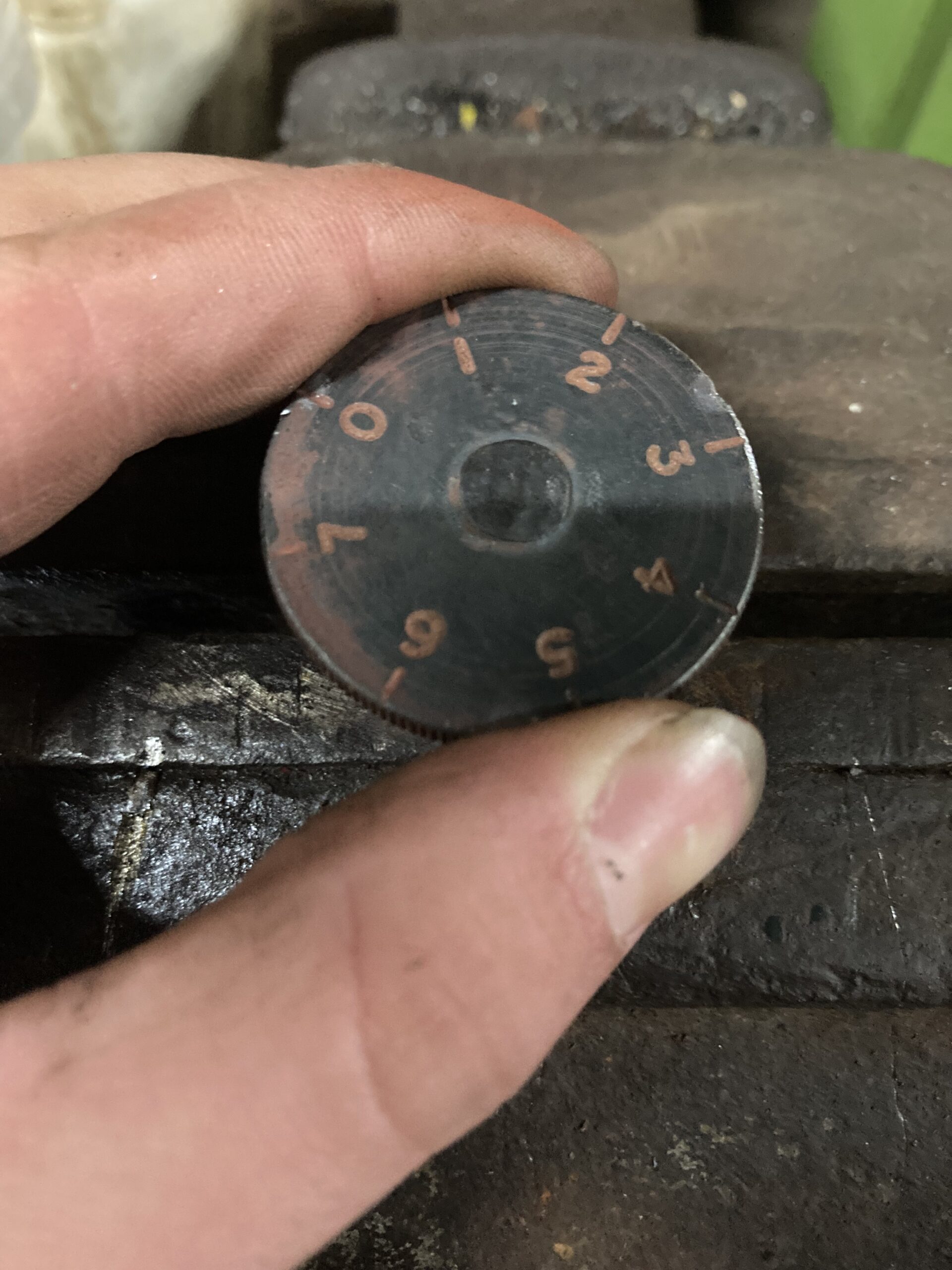
The removal of the dial from the broken shaft. This was done in a drill press with a 7mm, 7.5mm and 8mm drill in that order, gently cutting away the riveted over end of the shaft. Then with a hammer, punch and a hardy hole of an anvil, (which is conveniently just smaller than the diameter of the disc) the broken part was removed.
Job 2:
To save the screwed component and original needle, it would have to be jointed to the repair piece. the decision was taken to remove the snapped off remnants down to a flat surface in the lathe and then drill into the end of it, with a centre drill initially then followed by a 3.5mm drill, using the tail stock of the lathe to get the hole down the centre of the shaft, made easier with some CT 90 cutting compound (am unsure what the original metal is, it looks cast but not like iron).
Job 3:
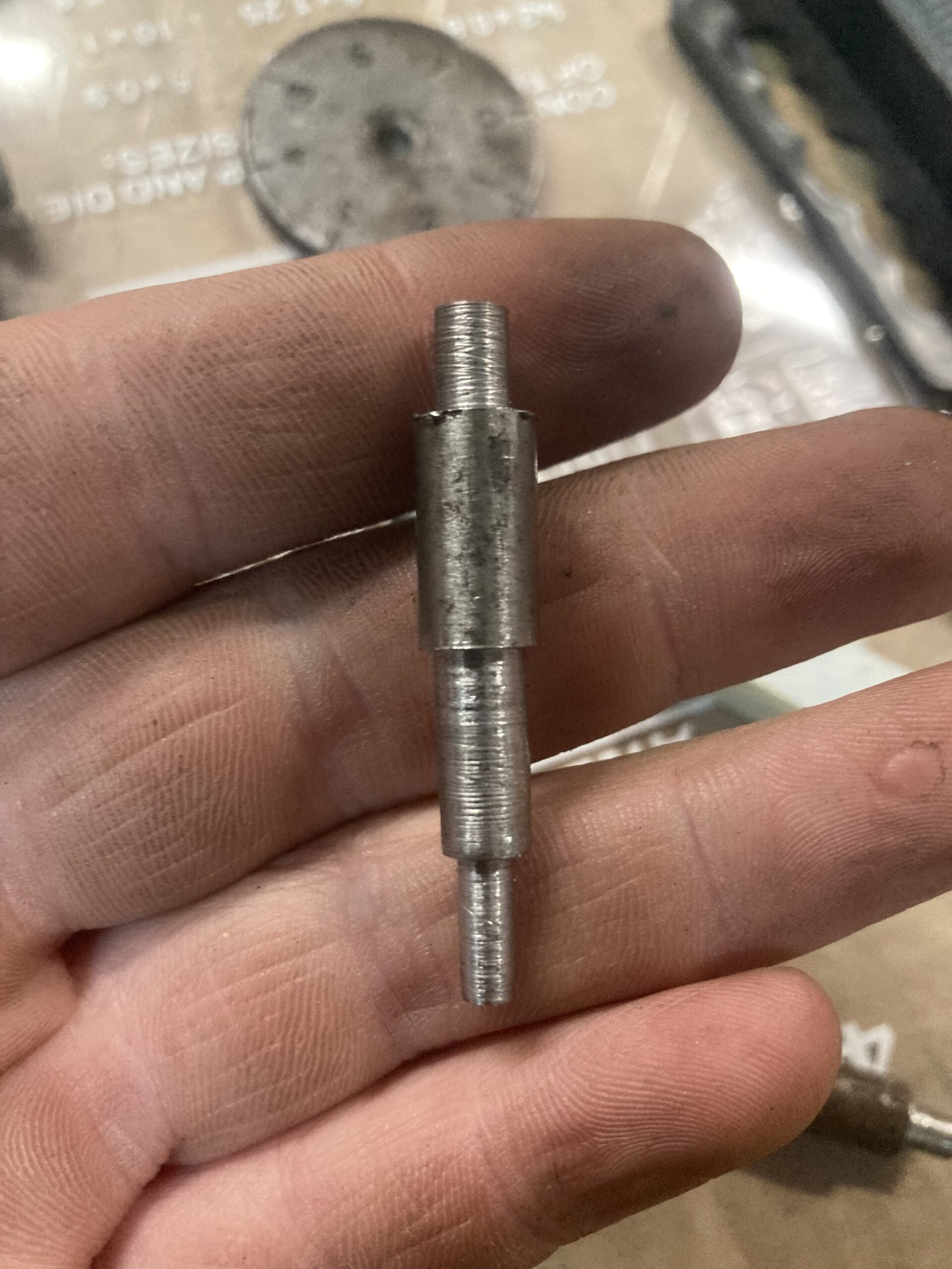
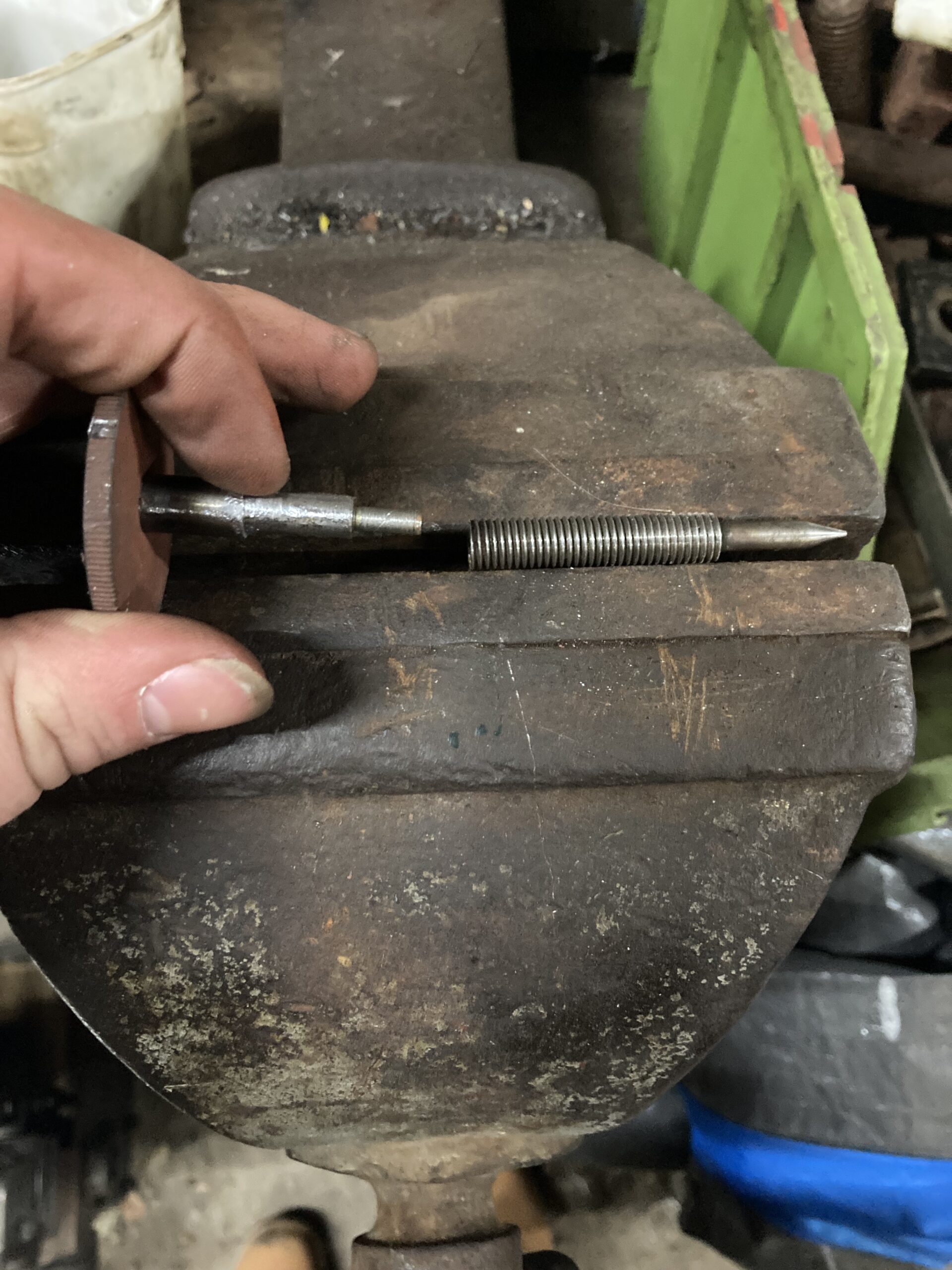
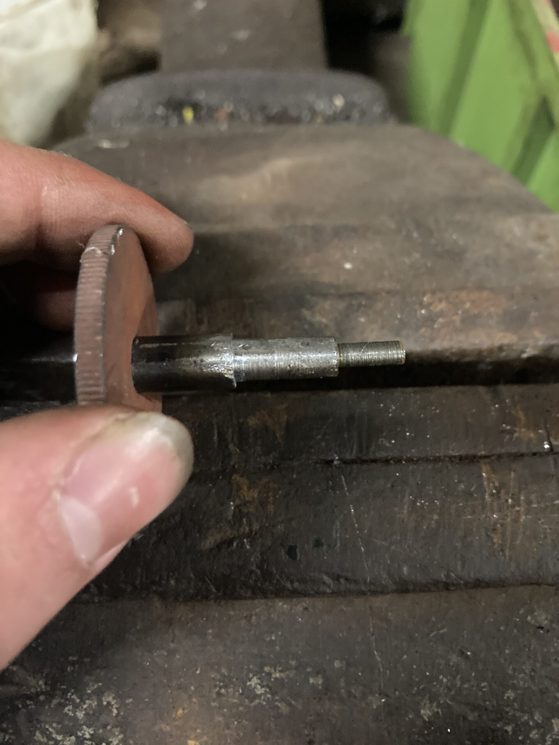
The repair piece itself. since this piece was going to have no overall effect on the operation of the fuel needle inside the carb, its exact accuracy in length was not essential, but made to be as close as I could. I started with isolating the roughly 3mm section at one end that would slot into the dial and be peened over. Then focus was changed to that of the 3.5mm shaft section that would be slotted into the fuel needle section. This is where the failure occurred and progress was back to square one. However, after getting to this point again, with shaft finished this time, the main section of this piece that will ultimately slot into the fuel jet was addressed as it had to be smaller in diameter than that off the threaded needle piece to be usable. the threaded piece was about 7.5mm diameter so the repair piece has been made to 4.5mm to give it clearance.
That was an exciting milestone as the machining was complete and a kit of three parts was prepared for assembly.
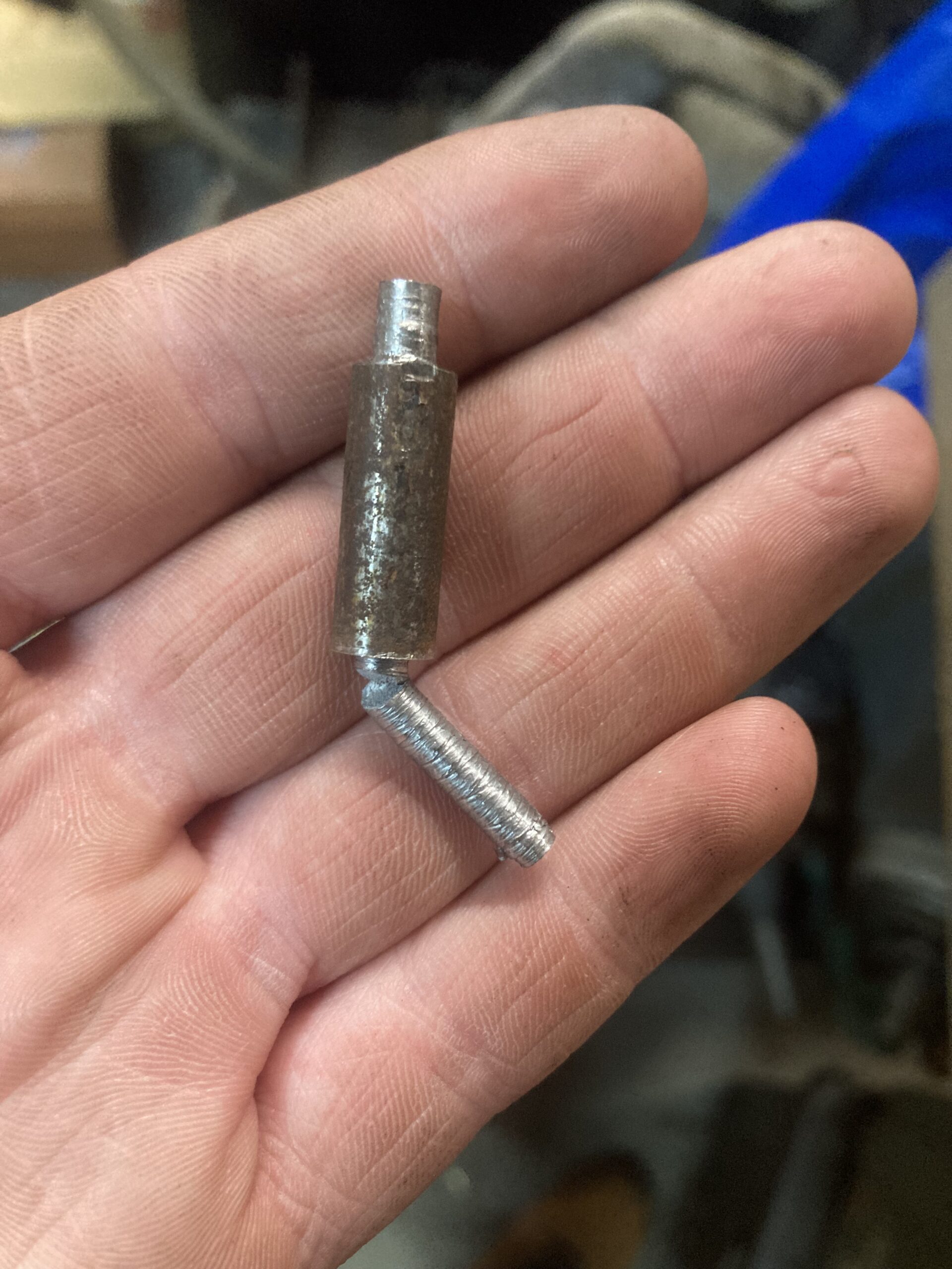
Job 4:
Now for the exciting part. Assembly. I started with the dial and repair section. The dial was press fitted to the repair and then the whole component held in the vice. I then gently warmed the section to a glowing red with use of a Rothenberger Map gas blow torch, a penned over with a ball peen hammer. As for the connection between screw thread and repair section. Due to the lack of knowledge on the threaded parts metallic nature, the choice of silver solder was taken.
You must be logged in to like this post.
Country: GB