Restoration of a number 3 Lowne atmospheric engine. ( flame gulper )
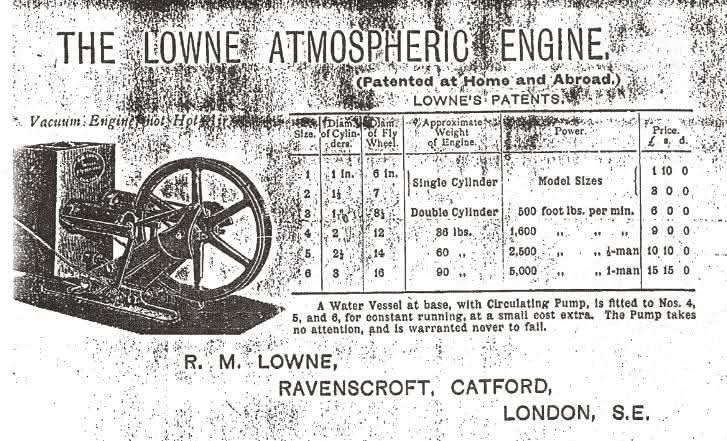
Looking more like something dreamt up from the mind of W Heath Robinson than an engine, this assemblage of moving parts was a small prime mover for the wealthier members of mid Victorian society. There are currently only two known surviving examples. The Lowne patent was built under licence by Hardy and Padmore of Worcester, but this machine was built by R M Lowne’s instrument makers London England.
This last few months I have mainly been relearning the skills that the multiple strokes have taken away from me. Driving the lathe and milling machine, grinder and pillar drill. My fine motor skills are still rubbish but they ARE improving very slowly.
My recent acquisition, a number 3 Lowne patent Atmospheric engine has been the subject of my relearning processes….
A couple of years ago I acquired a number 2 Lowne patent atmospheric engine on eBay. The engine was incomplete missing its pushrod and port face valve flap. These little engines are quite rare, but as luck would have it an old friend of mine had a number 3 motor in his possession. After several phone conversations and even more photos and measurements I was able to fabricate the missing components and get the engine to work properly again.
During our conversations, my friend told me about a gentleman that had also bought a number 3 twin cylinder engine in a near complete state. Subsequent conversations revealed that it too was missing both pushrods and one of the cylinder port face flap assemblies. With the photos he shared I was able to fabricate the missing gas pipe layout for the single.
As time goes by we are all affected by life changing events. A serious health issue occurred and as a consequence the near complete Lowne number 3 engine became available to me. A deal was struck and the engine was packed into a box ready for the courier.
The following day it arrived safely on my doorstep.
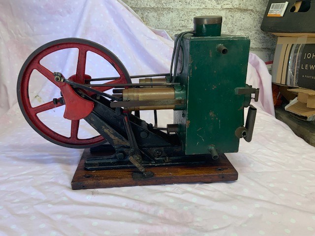
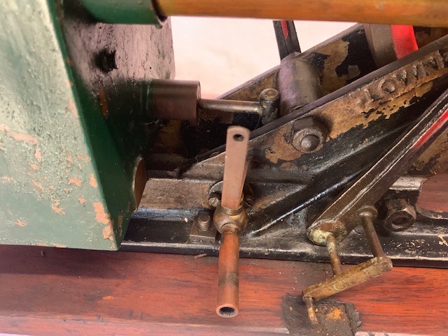
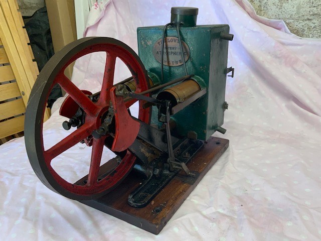
I’m sure you folks can see the rather strange circular object perched precariously atop the cooling tank? This turned out to be a cylinder lubrication system fitted by a previous owner. I’m not sure if I’ve mentioned the fact that the pistons are not a machined fit to the cylinders? They are sealed using a crude spring loaded stuffing gland on each side. These would have used thin Leather rings,lubricated by Sperm Whale oil. The cooling tank had also been modified by sealing it up and fitting extra pipe outlets for even greater cooling capacity. This aside, underneath the oil box cover I discovered nearly all the parts associated with the missing pushrod assemblies. The time had come to start upon the restoration process. The pushrods were the first to be attempted. When I tried using the one I had made for the single cylinder engine, I quickly learned that I had not used the right thread. In fact several different dies were tried to no avail. The breakthrough came when I found one of the screws used to attach the gas tap to the framing fitted snugly on the locking nuts. It was Jason Ballamy that did the detective work from a photo I placed on the MEM forum. It turned out to be a gauge 10 Thury thread. The Thury system was used primarily for instrument makers of the later Victorian period and actually became the basis of the BA system still in use today. The closest equivalent ended up being a ‘ rounded off ‘ 4 BA. Having finished the first pushrod it was time to see if we could get the first signs of life out of the engine. I spent several hours adjusting the position of the arm to set the timing. It just wasn’t having anything. Only after asking Alan what the hell was I doing wrong did the answer come, ‘ it’s not you Dad it’s what someone else has done ‘ I hadn’t noticed that there were additional pivots and arms fitted to the rocking lever. For some reason, still to be understood, the owner had added a pin that ended up putting the timing out by 180 degrees! They had even butchered the wooden plinth to accommodate the change. The modification had been well executed requiring some serious heat to break down the hard soldered joints. It took but a few moments to reset the timing and the flame applied to see her running for the first time in many, many years.
Over the next couple of weeks I started making the rest of the missing components. The surviving flap had been stood idle for so long that the Asbestos washer had welded itself to the port face. Upon close examination it was very nicely made with a thin Copper foil backing. I decided to just remove it and make a plain Brass flap instead.
At this point the remaining missing pieces were made using the original parts as patterns. The only difference was that the RHS flap was handed in the opposite direction. A couple of flat section Neodymium magnets were used to keep each pushrod pivot in contact with the piston lever arm because the owner had cut the ends off for his/her modification. At this moment I’m not sure of which direction I should take to repair the damage. It only needs around a 1/4” of an inch of metal with a small cross drilled hole for a retaining wire and washer.
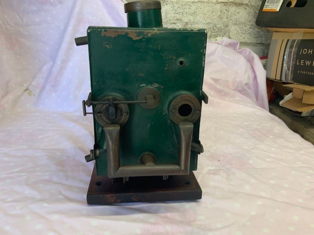
Now the engine was running on both cylinders we turned our attention to the rather ghastly looking, pissed up oil box. We initially tried to straighten it out but it was fabricated from some very thin Brass sheet and immediately distorted. Out came the small gas torch and within a few minutes the whole top collapsed in on itself. Underneath we discovered that there was a Brass pipe that was placed to ensure that the tank was filled to a certain level, the overflow situated at the front face of the engine. We had no choice but to rebuild the top back to its original form. Before this we removed the two short pipes that had been installed for the extra cooling and soldered a couple of Copper patches over the holes.
Now finally finished, my work is done. The next step is, do I leave it like this or fully redo the paintwork? Decisions, decisions….
You must be logged in to like this post.
Country: GB