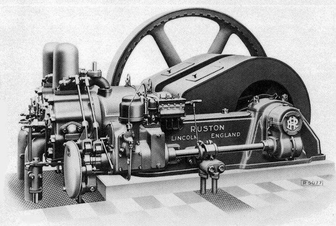
Like many, I love to wander around the steam shows looking over the frequent displays of venerable old Ruston and Hornsby horizontal diesel engines, many thousands of which were built and shipped to all corners of the world in the first half of the twentieth century. I ‘m always fascinated by the smoothness with which they run, and almost hypnotised when I look at the rim of the huge spinning flywheel, so accurately machined that it appears stationary.
My memory inevitably takes me back to when I served an engineering apprenticeship with that manufacturer in their multiple factories in Lincoln, England back in the late 1940’s. I can still see in my mind’s eye, the huge Bullard vertical lathes on which the flywheel castings, up to 72 “ in diameter, were machined on the perimeter and then at the centre for the crank shaft mounting.
As part of my training, I worked on many of the machines used to make various engine parts. One of my early assignments was the machining of the huge piston castings for the horizontal engines in preparation for the finish grinding. The castings were so heavy – the pistons were up to fourteen inches in diameter – a hoist was needed to lift them into the lathe. As the core of the casting mould was not always central, first operation in the lathe was to measure the variation in wall thickness and offset it in the four jaw lathe chuck so that when machined on the outside, the walls of the piston were of equal thickness all around. If the core was out one quarter of an inch, it meant that the first roughing cut on the outside could be as much as half inch deep while minimal on the other side. After machining down to within .020” of finished diameter, the piston ring grooves then had to be cut. If the centring of the piston was not done accurately enough, one could find the ring groove tool penetrating through the piston wall on one side – a sure way to bring the foreman’s wrath down on one’s head. The final operation was to machine the convex shape of the head to match a template, honing one’s skill at simultaneously moving the cutting tool in two planes to obtain the right shape.

The engine side shaft operating the valves on the Ruston horizontal engine is driven by two to one ratio spiral helical gears on the end of the crankshaft. The gears are enclosed in a cast-iron housing, three pieces bolted together. One of my jobs for a while was to machine the end cap hole and the shaft bearing hole after the housing parts had been milled, drilled and bolted together.

As I look at the restored engines, I often wonder if I am looking at pistons or gear housings that I machined myself many years ago.
You must be logged in to like this post.
Country: GB