.Or…. The kit that never was.
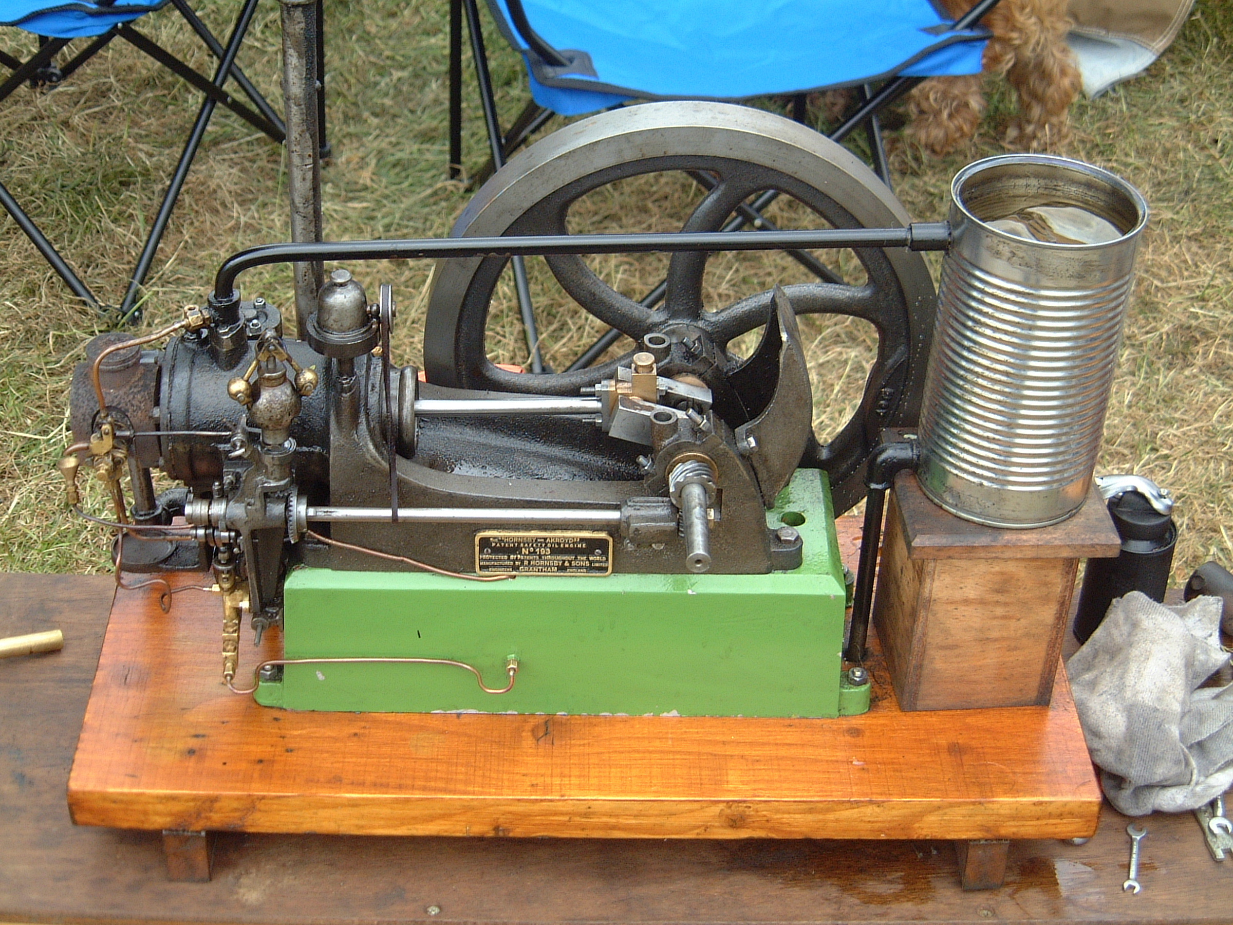
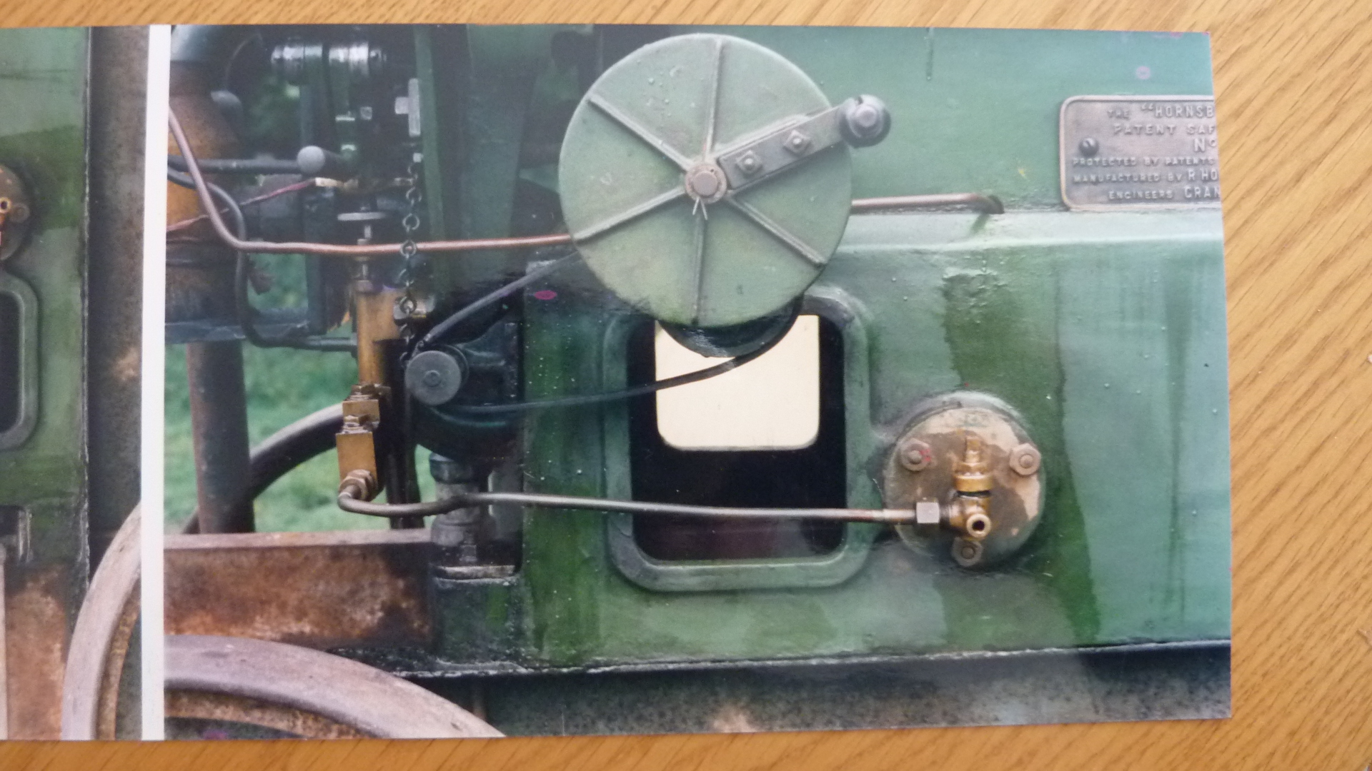
Sometime around the Millennium, I decided to make a replica of a friend’s Hornsby Akroyd oil engine. Richard had acquired this engine from a local collector known affectionately as Doctor Tom. Engine number 193, a 2.5 HP Oil engine, had originally been built and shipped out to R. Hornsby and Sons Ltd Buenos Aires showrooms where it stayed for several years, never having been sold. The engine eventually being shipped back to Great Britain where it remained. I’m not sure if it ever did any real work but it ended up being kept by Ruston Hornsby Ltd as an exhibit in their head office showroom.
A Brass plate was fitted to mention that the engine had been mechanically restored by Ruston Hornsby apprentices in the 1960’s. It was interesting to note that this engine being only the ninety second of the production run had several castings with an X suffix in the part numbers. I always wondered if the X stood for experimental and that they were improving the engines as they went along
We spent many a happy hour on the NW rally scene tinkering with this rather pernickety exhibit never actually knowing if it would behave itself for even a couple of hours in each day! Looking back, only the Lord knows why I even contemplated the thought of making a replica….
For those who might not be familiar with this type of engine, the design is attributed to a Mr Herbert Akroyd Stuart, a pioneer in the evolution of the ‘Safety ‘Oil Engine. He developed a way of igniting the much safer, less volatile lamp oils of the day by using a combination of heat and pressure. A low-pressure equivalent of the now well-known compression ignition principle. At the end of the cylinder, the combustion space is constricted down to form a bulb. This bulb is then heated via a lamp up to the temperature that the oil vaporises at. On the induction stroke, air is drawn into the full cylinder volume. At the same time a medium pressure pump delivers a preset volume of oil into the bulb via a sprayer nozzle thus atomising it. On the next stroke, the compression stroke, the now atomised fuel mixes with the air and at a certain point, determined by the pressure, the mixture auto ignites. The next stroke is the power stroke before the final exhaust stroke completes the cycle.
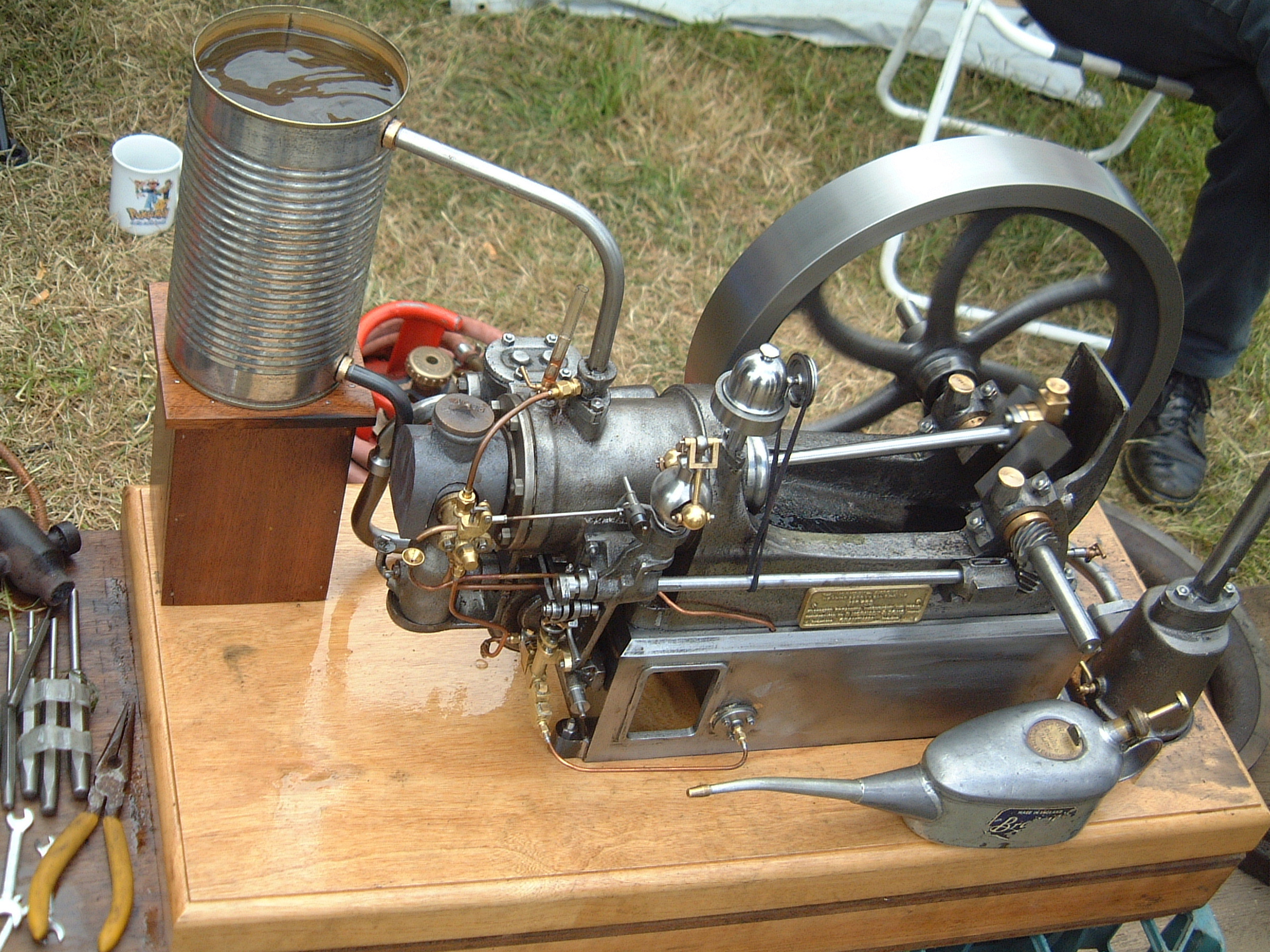
I should perhaps mention in greater detail something about the starting lamp. I believe that the Akroyd engine predates the invention of the pressurised Paraffin blow lamp? As a consequence, an interesting and serious crowd-pulling alternative was developed for heating the bulb. A cast Iron pot with a large wick in the bottom was filled with Paraffin up to a level determined by a plug in the side. The Asbestos wick was then lit and allowed to heat up the fuel. After a few minutes, the driver would then start to turn the handle, slowly at first building up speed as the fuel vaporised. This handle was in fact the drive, via an epicyclic gear to a centrifugal fan mounted below the cylinder. The fan’s outlet was loosely connected into the side of the pot, the pot sitting on a stand directly below the bulb. The driver would remove the cap from the bulb shroud to allow the now roaring inferno to fully heat the bulb. A small drop of Paraffin dropped onto the top of the bulb would show if the heat was sufficient for starting.
The engines speed is regulated by a flyball, centrifugal governor running at just a fraction over crankshaft speed. The action of which opens a spill valve attached to the sprayer. A small funnel is used to direct the spilled fuel back to the base fuel tank. Once the engine has been put under load the heat generated by the combustion process is enough to keep the bulb hot enough for use without the starting lamp.
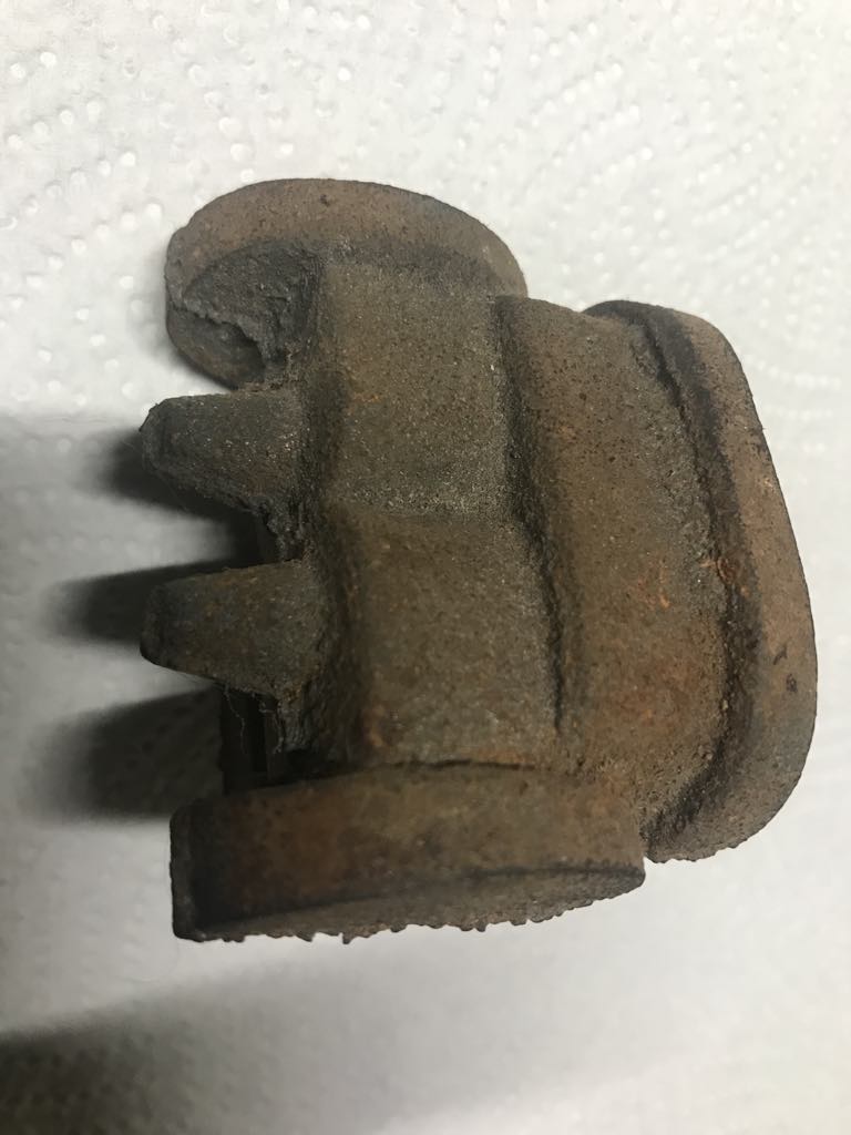
I love flywheels – it’s one of the first castings I machine whenever I get a new engine to build. It stands to reason that this would be the first pattern to make. This pattern took me nearly a month to make. Straight spokes are really quite straightforward, once you have the dimensions sorted. This one has curved spokes. That meant I had to make twelve halves, six in one direction and six in the other. In case the reader is wondering why twelve spokes, the pattern was being made in a split form to aid the moulding process. A spoke was then measured in several places and a single piece of wood was carved into those dimensions. The carving was then moulded in sand twelve times in order to cast twelve individual Lead spoke halves. These halves were then paired before gently bending them into the required curved-shape. We now had six left hand and six right hand halves. My next task was to prepare the rim. This was made from 13 Ply to the inch plywood, machined on the lathe at just under twelve inches in diameter. The problem now arose as to how I was going to align all these components accurately. Vincent to the rescue. He suggested first gluing the rim onto a square of picture frame glass. Being really thin the parallax error would be greatly reduced. Using a pair of dividers, the hub position was next found and a wooden boss machined to the correct diameter and glued in the centre. The tedious bit was then marking out the sixty degrees spacing on both the large and small diameters. After a great deal of time and patience, I had the vestige of a flywheel glued to both sides of the Glass. The next job was to then blend in the spokes, at both ends using good old car body filler. The glass helped me ensure that the blending matched with near perfect results. The final job was to make and match the two counterbalance halves between two of the spokes.
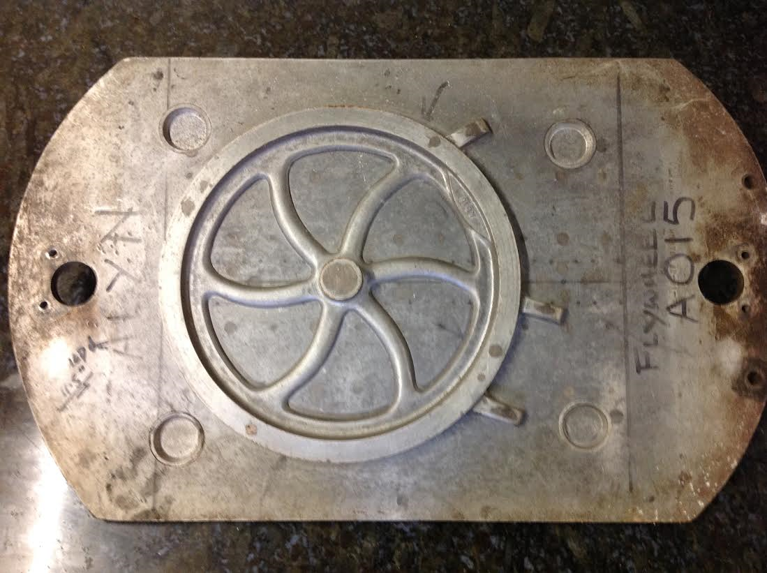
Are we there yet, are we there yet? No not quite. All that remained was to now cast each half in Aluminium, carefully align each half and fit them to the moulding plate. This was definitely the most tedious pattern I have ever made and or, I ever will. Now with the aid of CAD and 3D Printing a curved spoke flywheel takes but a few hours instead of days to make. And is a damned sight more accurate.
The rest of the pattern making for this quarter scale model was pretty much straight forward. Just a matter of taking measurements and allowing for the double shrinkage.
Double you ask? Yes, we have to account for the Aluminium masters and the finished Iron components. In all, it took me around nine months to finish all the patterns. Made from wood before running off the Aluminium masters.
I had to make several Aluminium core boxes because of the small scale. A special, heat-activated core sand was required to ensure they didn’t break up during casting. The bulb has internal finning just like its full-sized counterpart.
I do remember having to rush a bit during construction because the Rhuddlan foundry had announced that it was closing its doors after 150 years of production. This meant that several of the larger components ended up coming home still glowing in buckets of sand to stop them chilling.
By now I had also got an amazing working relationship with the Buckley foundry who allowed us to go in on a Saturday morning to mould up any patterns that we needed casting and were usually made ready for us to pick up the following week. All the Brass components were made at Madeley Brass castings, a cracking firm with whom we’re still working with forty years on.
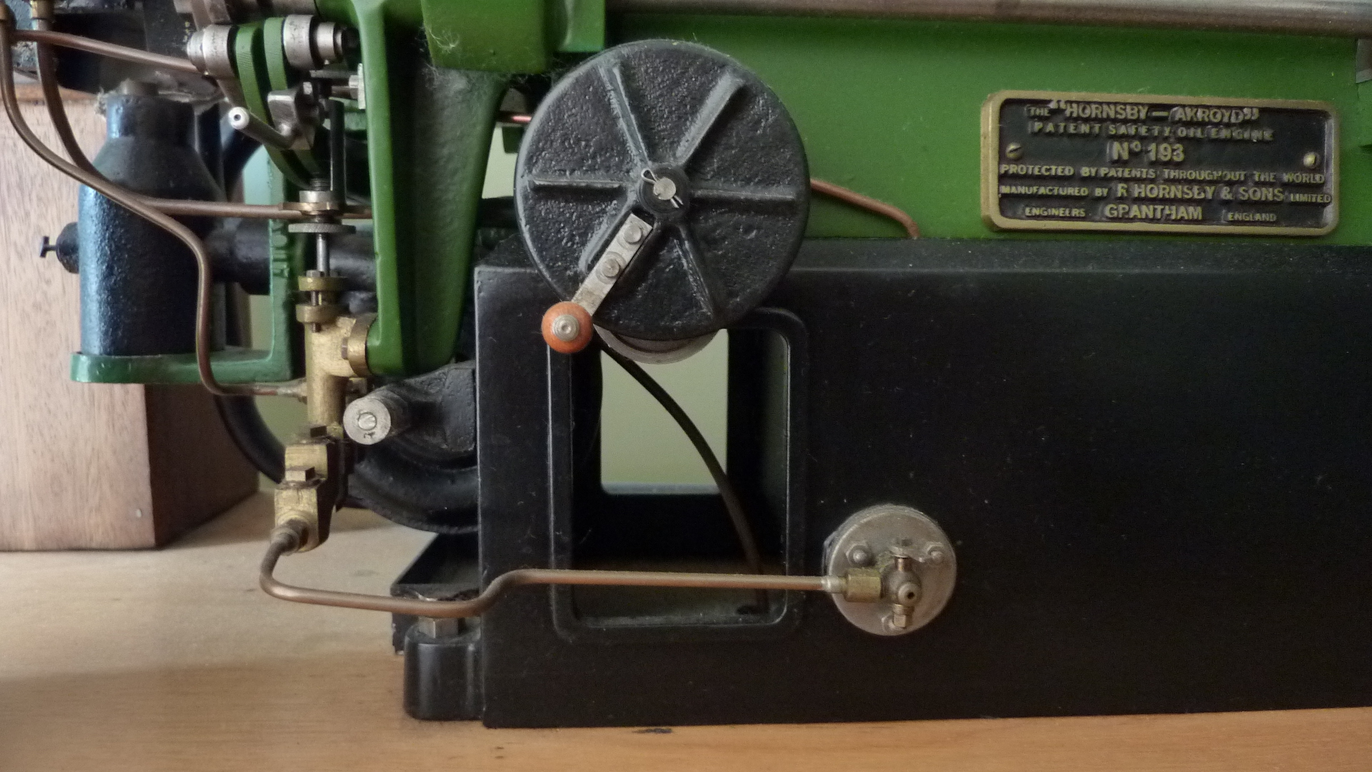
The badge pattern was produced on the PC converting the digital image into a photo etched plate, using the services provided by Madeley Brass.
The side shaft gears were made by Woollacott gears who have sadly recently ceased trading. The governor bevel wheels were provided by HPC gears of Chesterfield Derbyshire.
I won’t go into major details around the construction, sufficed to say that it went together reasonably smoothly and systematically. The less can be said around it’s commissioning. I had, had this been in my bonnet that the fuel pump plunger would need to be upsized because of the small scale. Nothing could have been further from the fact. The first tests made so much smoke that after a short while I could not see my hand in front of my face. This was one of the few occasions where my dear wife banished me from the house until I had bagged up all my clothes and spent a long time in the shower room. There’s nothing worse than the smell of unburnt Paraffin. Needless to say, the engine ran on the 1/8” diameter plunger at exactly one quarter scale.
The model was not a great success, sadly it had inherited all the foibles of its full sized mother. It would run flawlessly for a time and then just be an absolute pig. Being such an unreliable engine, I decided that to market it would be financial suicide and totally jeopardise our great reputation. Nine months of laborious pattern making work now sits gathering dust on a shelf in the workshop.
Ultimately, there were just two engines built. Mine, and my good friend Dave Allen’s. We exhibited them together at Astle Park, though, as the years all blur into one, I cannot recall the precise year of the only outing of the Ackroyd twins.
You must be logged in to like this post.
Country: GB