Over the last 15 years or so I have built a couple of crank guards for my own engines were it is next to impossible to find any for sale. These were for a Ruston 7IP and a Crossley G110, in both cases they were done with basic tools except for a hand operated rolling machine and in the case of the Ruston Crank Guard the brass tube edging was slit on a milling machine.
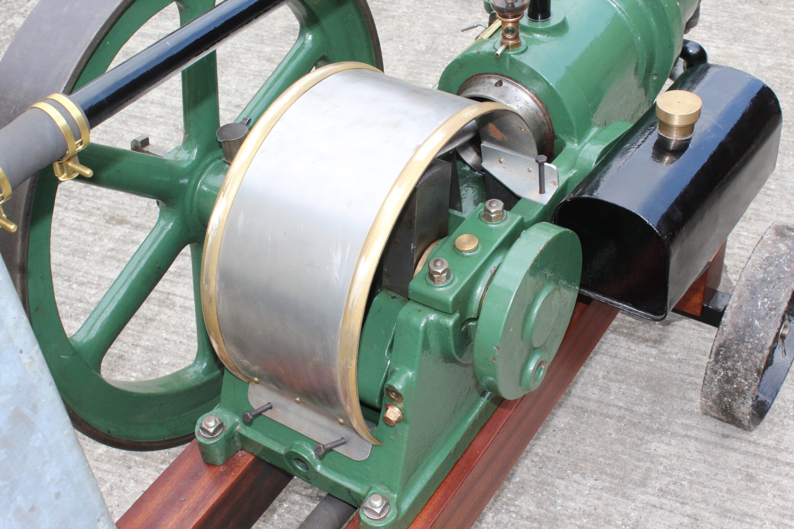
About 7 years ago Mike my middle son purchased a Fielding & Platt oil engine which was missing its crank guard and I was asked if it was possible to make one. The answer was dependant on how complex it was (double curves as per a FMZ or Ruston PR are outside my scope). After checking with the Fielding & Platt guru Trevor Hill it was established that it was only a curved sheet of steel with some half round beading riveted along the edges. An owner of another engine of the same HP, Pete Miles volunteered to allow us to take dimension of his crank guard and many photos. Thanks to you both from Mike and myself.

Materials were ordered and because I stated that the width of the steel sheet was critical, they laser cut it for accuracy at no additional cost (thank you m-machine-metals.co.uk of Darlington). Once the sheet arrived all we needed to do was cut to length.
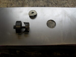
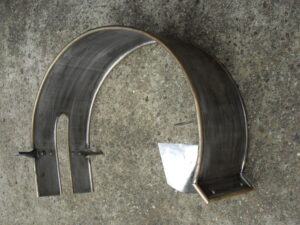
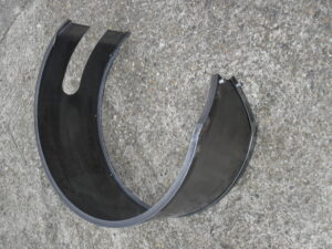
I have always started with the cut-out for the con rod, and the sheet was marked up for this. I am fortunate that in all three cases the cut-out was 1.5/8” wide and I have a Q-Max cutter this size so can get the radius at the top end using this. If not then chain drilling and filing is the order of the day, which needs a lot more patience to get it looking right. Using a jigsaw, I did the long straight cuts and then filed to the line. It was then on to cutting to shape at each end, again using the jigsaw and a file. Once satisfied that all was in order all edges then needed to deburred. The front angle mountings were made to suit as per the sketches we had taken from Pete’s guard
.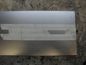
Before rolling the sheet and beading to the required shape the profile was drawn out on a piece of plywood. This helps with getting the shape right of all the parts. Rolling is just a steady gentle bending process and will require the metal passing through the rolls many times with adjustments to the rear roller to get the required shape, checking regularly with the wooden template.


The brass beading was then rolled in the same way.

The edges of the sheet steel were marked 3/8” from the edge along both edges, the rivet holes will be drilled along this line for the brass beading. Starting 1/2” from the end holes were marked at equal pitches to finish ½” from the other end. A total of 9off equal pitches as per the one we were copying off. The 2off additional holes for the front brackets were also marked and all holes were drilled to suit the rivets, M4 in this case.
The front angle mountings were set up using clamps and another piece of angle to ensure they ran across inline with each other. Rivet holes were then transferred from the steel sheet into the brackets.

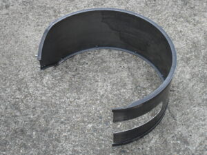
The brass beading was positioned with one end against the cut-out at the front end and clamped to the sheet steel, a second clamp was added about 2 holes further along and adjustments made until the beading was true at the end and along the edge and a couple of holes transfer drilled into the brass beading. M4 screws and nuts here then fitted to these holes and the clamps moved further along and more holes drilled adding screws and nuts as I progressed. Once all holes are drilled it was time to mark the other end of the brass beading ready for trimming to length, then remove the beading and repeat for the other side.

Once both were cut to length the holes were countersunk to suit the rivets and all holes deburred.
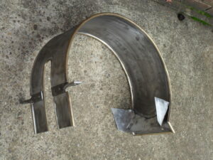
The kick out at the back was bent using a folding machine but can be done with care using a vice. The brackets and beading were assembled as before with screws & nuts with every other one left out ready for the rivets. Once all the vacant holes have been riveted then screws & nuts can be removed until all rivets are done. For the half round rivets, I have a die to suit the head shape that was made may years ago using silver steel on the lathe. All the countersink rivets need the heads cleaning carefully using a file with emery cloth to finish.
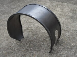
The crank guard was offered up to engine to check for fit etc and the 4off mounting holes were marked as per the engine. I did this as on both the Ruston & this engine the holes are not equal about the centre line as would be expected.
The oil drip strip to ensure most of the oil returns to the crankcase rather than running down the back of the engine was mocked up for drilling and riveting off the engine.


Below are the different methods used to complete the differing styles of crank guards, the steel sheets for each were done as above.
Ruston IP
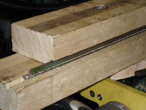
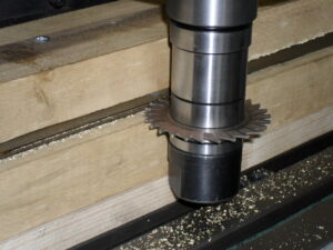
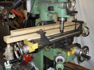
The Ruston crank guard for my engine needed the brass tubing edging and twisted flat steel supports. The cut-out for the con rod was edged using ¼” brass tubing which I formed round a wooden pattern (cut-out of plywood on a base piece of plywood) and should be slightly longer than required. It was then clamped to the former and using a 1/16” thick slitting saw cut on the outside edge all round. The rest of the crank guard needs to be in 3/8” brass tube and this was cut in exactly the same way but before shaping. It was then rolled to shape on the hand rolling machine were necessary.
Suitable pieces of steel were on stock for the two front mountings and were marked out according to the sketches I had been able to make from another crank guard. The steel was heated with a gas blow torch until cherry red (a barbeque will do the same job) the it was quickly transferred to the vice and using two adjustable spanners set as a T lever the steel was twisted through 90degs. When doing the second one remember to twist it the opposite way to get a handed pair.
The twisted supports were fitted as per my sketch and then the brass tube, remember to clean the steel and flux up before fitting. It was then down to lead soldering. Both sides needed doing, about 6metres altogether. Holes were drilled at the back end of the crank guard to suit the tapped holes in the crankcase, in my case they are off centre for some reason.


Crossley G110
The Crossley crank guard has two angle iron rings riveted to the outside of the steel sheet. These are a bit specialised to obtain, I found a ring rolling company in Bradford, and ordered what I needed. When ordering you specify the size of angle and whether you what the flange on the outside or inside, mine was the latter. On arrival the rings needed a curve in at the back end as the crank guard got narrower. This was achieved by placing saw cuts close together of a short length, closing the cuts up and welding. These were then cleaned up and checked, all was good. The rolled sheet then needed to be trimmed to suit this shape. Rivet holes were marked out on the angle at the correct pitch and all holes drill and deburred. The steel sheet was clamped to one of the angle rings starting at one end and the first rivet hole drilled and a nut & bolt the same size as the hole fitted. Checks were made to make sure the steel sheet sat against the angle ring and clamps adjusted as required and the next hole drilled, again a nut & bolt were added. This was repeated until all holes were drilled, then repeated on the second ring. All were then undone and the holes in the angle were countersunk for the rivets. With all holes deburred and metal cleaned the items were reassembled with every other bolt omitted and riveting commenced. When all vacant holes had been riveted then the nuts and bolts were removed and these holes riveted. The rivet heads were all cleaned of flush with the angle. The back end of the crank guard had 2off ¼” diameter pins fitted to coincide with 2 location holes in the crankcase.

You must be logged in to like this post.
Country: GB